W5RWF 160 METER ANTENNA 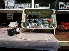
I was showing Ed the Antenna Tuning Unit (ATU) and radiator for my 160 transmit antenna and he suggested I write a few words on how it came to be. This is not a construction article, just a few paragraphs on how I perceived the problem, the concepts developed to overcome it, and the operating prototype I’m currently using. 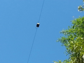
I am faced with the same problem as most of us when trying to set up antennas for 160 Meters. Karen and I have a nice, but typical, suburban lot that is not quite big enough or shaped well enough to support a worthwhile 160M antenna. I don’t have the space or height available for a credible dipole so I modeled a shortened, loaded, dipole in EZNec V5 and the support height available on the ends would not allow for any kind of worthwhile performance with that configuration either. A quarter wave inverted L was next modeled and the performance was very good, but the required radial field would not work on my lot. I then looked at an inverted L loaded to an electrical half wave which requires a much more modest ground as the return current does not have to pass through the earth. The EZNec models were very promising with the elevation plot showing slightly more radiation at low angles and an overall gain only about 2 dB or so less than a typical dipole. There is no substitute for height and wire in the air, but this seemed to be a step in the right direction. 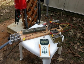
At this point I was encouraged but the high driving point impedance and the narrow bandwidth were both challenges. I approached both of these hurdles with a remote controlled antenna tuning unit located at the base of the tower and a remote controller in the shack that would both operate the electric screwdriver used to drive the variable capacitor and also indicate where in the band it was set so that I would know which way to run the tuner when QSYing. The impedance was so high and reactive that EZNec would not calculate it, so I built the wire and the loading coil; 144 feet of wire and a lot of micro henrys of loading coil wound on a 4 inch PVC form, hung it in position, and then measured the actual resistance and reactance using my Rig Expert AA-54 analyzer. These values were recorded from one end of the band to the other and then entered into “MicroSmith”, a very old DOS Smith Chart program, and the required matching network was developed. I settled on the common capacitor, inductor, capacitor pi net configuration, as the L networks required would be more difficult to fine tune. Once I had the required network values in hand I used the RF calculation suite on the “Low Band DX’’ software CD and calculated the physical requirements for the matching components. 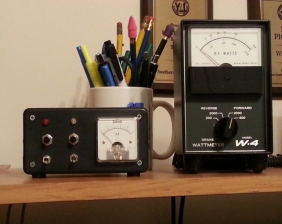
The networks were constructed, the control and metering circuits designed, built, and tested, and the prototype ATU was constructed in an “ultraviolet safe” container, sprayed with a uv opaque paint, and mounted at the base of the tower which also supports the vertical portion of the antenna. This summer will determine just how “ultraviolet safe” this assembly actually is. The remote control was installed in the shack and it tuned just fine, but with a minor linearity problem in the metering circuit. I worried with this for a time and made a circuit change, which helped considerably. To achieve perfect linearity is going to require a truly logarithmic meter driver and that’s a project for (much) later. 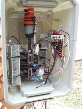
All of this seems to have had a happy ending as the antenna can be matched to a 1.5 to 1 VSWR or better, (most of the time much better) across the band. It does require remotely switching between two different values of padder capacitors, one for the lower portion of 160 and the other for the high end, but that’s no problem. 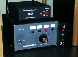
The actual tuning during operation uses an MFJ “Matchmaker”, an antenna noise bridge, allowing frequency to be changed and the antenna fine-tuned without radiating an RF signal. I do that with my other tuner as well since it helps eliminate the “tuner upper” syndrome. The Matchmaker is about $100.00 or so from MFJ and is a necessary part of any shack with a manual tuner in my opinion. 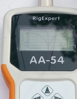
On air results have been encouraging. I’ve encountered no difficulty with the W1AW portable operations on 160M so far and the Puerto Rico contact was completed with one call on SSB. This antenna is no quarter wave vertical with 120 full-length radials, or even a half wave dipole a half wave high, but it seems to be working for me so far. When I become more serious about Top Band next fall I’ll find out how it really stacks up. 73, Bill… W5RWF | 


